I started out making wine with kits, and later decided to try making wine with fresh grapes. As I began planning my transition from kit wines to making wine from grapes, I knew that I needed to get a good grape crusher/destemmer. I found a few models that I could buy, which ranged from $300 used to $1,000 new. Then, I noticed a post in the forums on http://winepress.us that showed a homebuilt destemmer/crusher. The order of the machine’s processes was different, as the grapes are destemmed before being crushed. I found that an affordable hobby-sized version of this type of machine was not available, and I was not going to spend $2,500 for a commercial version. I looked at the machine that someone else had built and thought I could build one, too. Well, at least I thought I could try to build one.
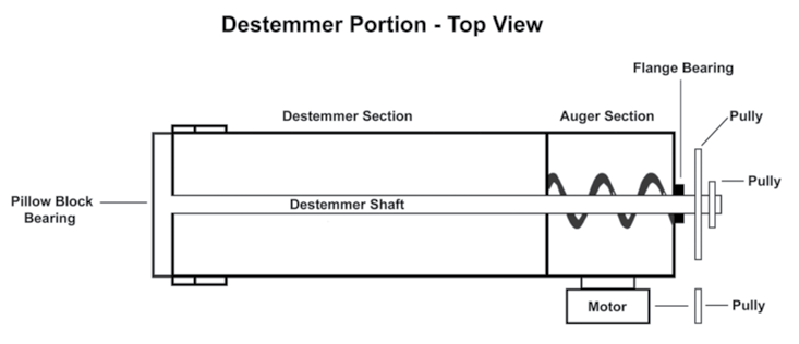
The first obstacle I had was that I didn’t have a lot of power transmission experience. By that, I mean the pulleys, sprockets, motors, etc. So, I knew I had some learning to do. Luckily, an article by Steve Hughes in the October-November 2011 WineMaker magazine had detailed how to build a crusher/destemmer, and a lot of the same principles applied. With that in mind, I decided to design my own destemmer/crusher — starting with the destemmer portion first.
Destemmer
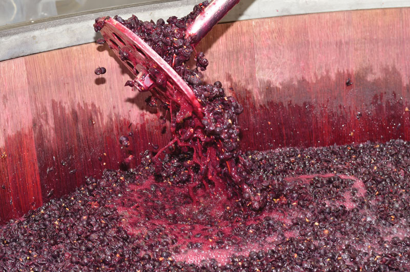
For the destemmer, the setup is essentially a set of “fingers” arranged in a helical fashion that push the stems and grapes out towards the end. The fingers rotate within a basket that has holes that are big enough for the grapes, but not for the stems. That way, the stems get pushed out the end, while the grapes fall through to get further processed.
The first step was to design the box, which would essentially be a compartment for dropping the grapes in to, and a section to house the destemmer. Based on what I had seen in the other DIY designs, the section to dump the grapes in could be small, about 14 inches (36 cm) long x 12 inches (30 cm) wide. The space for the destemming had to be a lot longer to ensure that it got all the grapes off of the stems. I determined that to be 36 inches (91 cm) long. This meant I had to make a box 48 inches (121 cm) long and 12 inches (30 cm) wide. To do this, I cut four pieces of 3⁄4-inch plywood. I then screwed the pieces together to form the basic box. The front and two sides were solid, but I had to cut a 12-inch (30-cm) diameter hole in the center so that the stems could be pushed out and the destemming basket would fit. To do this I simply drew a 12-inch (30-cm) diameter circle and cut it out with a jigsaw.
Next I made the grape compartment separate from the rest of the box by placing a piece of 3⁄8-inch HDPE and cutting a 12-inch (30-cm) diameter hole directly in the center. This is where the grapes would be pushed from the first compartment into the destemming portion. This was placed 12 inches (30 cm) from the front of the box. In order for the grapes to be pushed into the destemmer portion, I had to make an auger to push them along. This meant that the floor of the grape compartment had to be curved to allow all the grapes to be pushed through. In order to do this, I cut two semicircles of 3⁄4-inch plywood and placed them in the bottom of the grape compartment. This allowed me to push down a piece of 1⁄8-inch HDPE into those semi circles to create the curve that the auger would fit into (but I didn’t place that in yet).
At this point I had my basic box, but I needed a top to contain the grapes in the destemming portion. I wanted to make a removable top, so I cut a piece of 3⁄4-inch plywood 11⁄4 inches (4 cm) wider than the box and as long as the destemming portion. This allowed for a 3⁄8-inch (2-cm) overlap on each side. I then cut a piece of 1⁄8-inch HDPE sheet to go over this on the destemmer side. On the 3⁄4-inch (2-cm) overlap, I screwed in pieces of 1-inch (2.5-cm) dimensional lumber stock (actual 3⁄4 inches/2 cm). On this stock, I was going to place latches in order to hold down the top, but also to make it removable. So, I fastened the catch of four latches to the 3⁄4-inch stock. This completed the frame of the box.
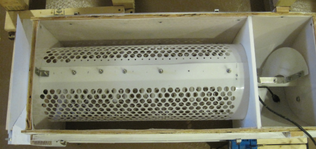
The next step was to make the basket for the destemming portion. Knowing that I had a 12-inch (30-cm) diameter, using the equation c=πd, this meant that the material had to be approximately 37 inches (94 cm) wide. Since I need some overlap to fasten it together, I opted to make it 39 inches (99 cm). Then came the tedious process of drilling the holes. The holes are 3⁄4 inches, and are spaced 1 inch (2.5 cm) apart. I drew a grid on the 1-inch (2.5-cm) intervals and the just started drilling with a step drill. After about an hour of straight drilling, I was done. Now, I had to fit it into the box that I built and then secure it together. Once it was in the box and conformed to the holes I built, I drilled eight new holes in the overlap portion to fit 1⁄4-inch x 20 stainless steel carriage bolts. These have the stud face upward, so the protrusion into the destemming section is only the rounded head. I then had to secure the basket to the box. In order to do this, I cut a piece of stainless steel and then bent it into an L shape. I then drilled a hole through the back plate of the box and through the basket, then made corresponding holes in the bracket. This effectively holds the basket in place.
Now that all of the static pieces were built, it was on to the shaft. The shaft required two sections, one for the auger and one for the destemming, but first I needed to get the shaft to turn in the box. The front was easy. I simply drilled a 1 1⁄4-inch (4 cm) diameter hole and placed a flange bearing against the outside of the box and bolted it in. The mounted bearings had a set screw, so I had no worries about it being secured. On the backside, I had to make a cross bracket to hold the pillow block bearing in place. I did this by having two 2 x 4 blocks on the outside of my box, and then cutting another 2 x 4 to go across. I then secured this by drilling two holes (one on each side) through the blocks and then putting 8-inch (20 cm) long carriage bolts through them. This allows me to remove the cross arm and do any cleaning. I then mounted the pillow block bearing on the cross arm (with two bolts drilled up through the cross arm). The biggest problem was that the shaft is actually larger than 11⁄4 inches (4 cm) in diameter. So, when you buy a HDPE rod, the size is greater than what it says. I had to sand down each end of the shaft in order for it to fit, which I did by hand and it was a tremendous chore. A lathe would have worked much better to get it down to the correct size.
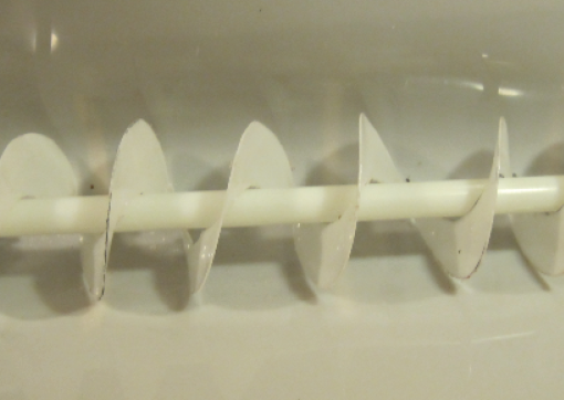
I now had to make the “fingers” for the shaft that would push the grapes through the holes. In order to do this, I marked for each finger to be 11⁄2 inches (4 cm) in distance from one another, and 3⁄4 inches (2 cm) of a turn. Once I made all of the marks, I used a milling machine to drill the holes. These holes are slightly larger than 1⁄2-inch (taking into account the larger diameter than what they are sold as). I then cut pieces of 1⁄2-inch HDPE rod at 6 inches (15 cm) and then inserted them in those holes. I then used some 1⁄2-inch (inside) diameter semi-flexible silicone tubing to fit over those rods in the shaft (see photo below).
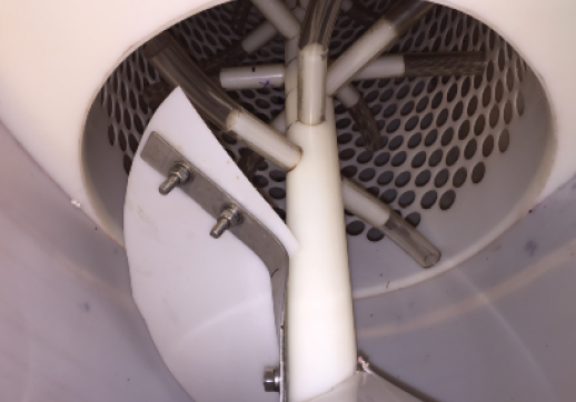
The next part was to build an auger in the front portion of the top part into which I could drop the grapes (see photo top, left). The auger would then push the grapes into the destemming portion. For this, I utilized the ideas behind an Archimedes screw. I simply took a sheet of 1⁄8-inch HDPE and cut it in an oval roughly 14 inches (36 cm) in diameter. I then cut a 11⁄2-inch (4-cm) hole in the center using a hole saw and then a single cut from the outside to the inside. I then slipped it over the rod and stretched it out. This indicated where I needed to cut it.
The inside hole had to be cut somewhat and the outside had to be trimmed. I tried using the Archimedes screw calculation, but it was easier to cut a little, try again, and cut some more. I then made two stainless steel brackets to hold the auger in place. These are bent at a 60-degree angle to accommodate the helical nature of the auger. I then drilled two holes through the rod to attach the brackets and two holes through each end of the auger. I put stainless bolts through these and tightened them. When spinning the auger, there was no rubbing and it pushed things along just fine. This completed the portion of the top part that was needed. However, I wasn’t going to crank this thing by hand.
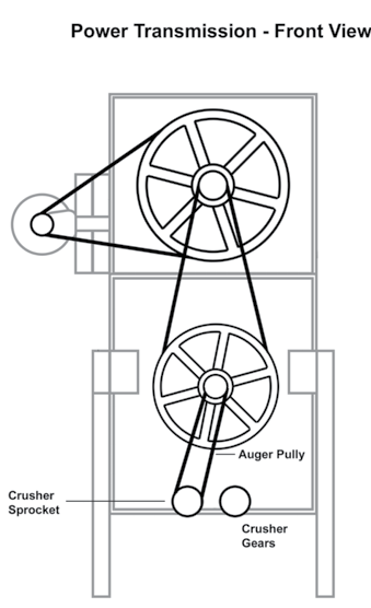
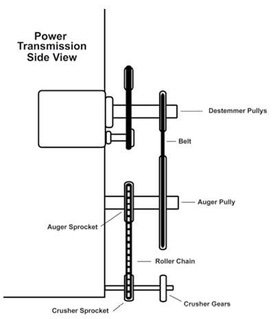
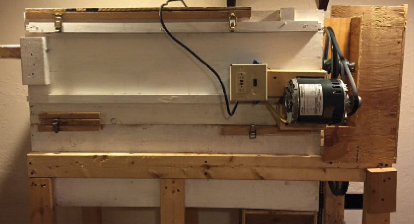
The next step was to attach the motor. I bought a new 1⁄4HP, 1,725 RPM reversible motor. I then placed a 2-inch (5 cm) pulley on it and then put a 123⁄4-inch (32-cm) pulley on the rod with the fingers then simply attached a V-belt. Getting the exact belt size required buying a couple different belts and deciding which fit best. I then hooked up the motor to a switch, which is powered by a GFCI (ground-fault circuit interrupter) receptacle to prevent any chance of electrocution.
An additional item for the top section is an angled chute to drop the grapes into the auger. This a 1⁄2-inch (1.25-cm) plywood box internally covered with 1⁄8-inch HDPE with 45-degree angles cut on the sides. I placed a 1⁄2-inch (1.25-cm) plywood kickstand for the chute as well to hold it in place. When the grapes go down the chute, anything that gets flung back by the auger does not make it back up the angle and into the face of the loader. This inherently limits the throughput of the machine. You can’t just dump a lug of grapes in and walk away. Bunches have to be fed one at a time, which limits the output. It takes about one hour to process 500 lbs. (227 kg) of grapes with two people. One person feeds the bunches into the machine and the other hands them lugs. If I was looking for more output, I would have to make some modifications (longer basket perhaps). Luckily, I only ever make up to 500 lbs. (227 kg) at a time.
The final piece for the destemmer was a box to contain the grapes that would be ejected from the end before they fall through the basket. To ensure that no grapes would be lost, I removed the last two fingers from the shaft and built a box chute for the end. This is built with 1⁄2-inch plywood covered with 1⁄8-inch HDPE plastic. It attaches to the rear cross brace for the destemmer rod with a couple of screws. Now, when grapes try to fly out at the end, they hit the sides of the chute and fall into a waiting basket to go back through the destemmer.
The tray
For the bottom tray, I needed to essentially build a section for the grapes to fall into and then an auger to pull the grapes towards the crusher. In order to do this, I built a plywood box, the same size as the top portion. I then made arches to be able to hold the HDPE sheet in a curved fashion. This would allow me to make an auger that ran down the middle to screw the crushed grapes towards the crusher rollers. I put in five arches, stopping 15 inches (38 cm) from the end of the box. First, I put a single piece of HDPE sheet on each end, extending all down the box. I then took a single piece of 1⁄8-inch HDPE sheet and laid it into the arches. I then screwed this into the sides. Next, I put a smaller piece of HDPE sheet on the last arch so none of the plywood would be exposed to the grapes.
The next step involved the auger. I utilized the Archimedes screw design again. I took a piece of 1-inch HDPE rod and ran it down the center of the curvature created in the arches. The top of the rod is 3 inches (7.5 cm) above the bottom of the arch. I had purchased 2 flange bearings (one for the front and one for the back) and then I drilled the holes for the rod and the bolts securing the bearings. The key was to line the rod up with the top rod so that the eventual pulley would be directly below the other one. Now I had to make the auger screw. I did this by making a cardboard cutout in a circular shape with a 1-inch (2.5-cm) hole in the middle. I then put it on the rod and stretched it. Then, I kept trimming it in the center and on the edges until it was pretty close to fitting. Next, I made seven discs of the same size and bolted them together with 1⁄4-inch x 20 stainless steel bolts. I placed the discs on the rod and stretched it out (like an accordion). I made two stainless brackets (one for each end) and then attached the auger to the rod. I tested it by spinning the rod to see where I had to do any trimming on the auger where it rubbed on the trough. Since the cuts weren’t perfect, I had to take some off and sand down some edges. Once I made sure the auger would spin freely, I added a small 103⁄4-inch (27.3-cm) OD pulley to the outside of the rod, making sure it would line up with the pulley from the destemmer portion. I also put a sprocket on the rod to eventually power the rollers.
At the end of the box (having left the 15 inches/38 cm at the end open) was where the crusher rollers were going to go. However, I now needed to build the frame to keep it off the ground so that I could put it on the crusher box. I attached a 2 x 4 to each side of the bottom box (with the auger) and extended it further past the box and into the pulley area. I used another 2 x 4 to attach the two boards together on the pulley side. I then built the legs. I knew I wanted to be able to put a Rubbermaid Brute® bucket underneath, so I made it high enough (making sure to take into account for the crusher box yet to be built). Also, since I wanted to be able to pull the bucket in and out, I left a gap on the bottom of the frame. This required a little extra work to make it stable (some additional cross bracing). Next, I put six casters on the bottom to make it portable. This allowed me to move it by myself, but more importantly, allowed me to now work on the crushers. The only drawback to this height is that the person who feeds the grapes must stand on a ladder in order to feed the bunches of grapes into the machine. It would be faster and safer if that function were closer to the ground. Obviously, this would remove the ability to place my actual fermenters under the machine. So, I would have to either manually transfer the must from a smaller bucket or buy a pump to move it if I decided to make this modification.
To build the crusher at the end of the bottom box (with the 15 inch/38 cm open end), I built a 17 x 10-inch (43 x 25-cm) box out of 1⁄2-inch plywood that had a funnel shape to it. To do this, I cut two pieces for the front and back, and then took one piece on each side and angled it so the grapes would fall towards the rollers. I then cut another two pieces to go straight down from those angled pieces to create the space for the rollers. I then covered
all of this plywood with 1⁄8-inch HDPE sheet.
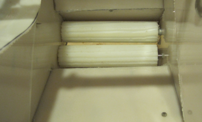
The next step was to create the rollers (see photo on page 51). The rollers are tricky. The first thing I did was buy two 2-inch (5-cm) HDPE rod pieces of 12 inches (30 cm). Thinking that smooth rollers may not pull the grapes between them well, I put grooves in the rollers so they would more easily be able to grab the grapes and get them crushed. To do this, I set up my router bench with a 1⁄4-inch straight router bit and had 1⁄2 of an inch (1.25 cm) of the bit sticking up. I then ran the rod over it, making an angled groove. I repeated this multiple times on each rod. The next step was to drill a hole down the center of each roller with a lathe. I made the hole slightly smaller than a 1⁄4 inch (0.6 cm) for one of the rods and a little less than 1⁄2 (1.25 cm) for the other. It was now time to assemble the crushers within the machine. So, I drilled two holes on each side of the box, leaving enough room for a 1⁄2-inch (1.25 cm) space between the rollers. I placed small nylon bushings in each hole to manage the wear and tear. I then lined everything up and put a 24-inch long (61 cm) 1⁄4-inch stainless steel rod down the center. This was slightly tricky as it involved tapping the rod through the box and into the crushers. The crusher holes were tight (on purpose), so I just had to tap a bit as I did not want to overexert and bend the stainless rod.
Next step was the gears for the crushers. I went to a website and found a free gear template and then printed it out and pasted it onto an old cutting board with a glue stick. At first, I used a jigsaw and the gears came out terribly. For the next try, I used a band saw and it came out much better. I then drilled a slightly less than 1⁄4-inch (0.6-cm) hole in the center of one and a slightly less than 1⁄2-inch (1.25 cm) hole in the other and slipped them onto the outside stainless steel rods. I then attached a sprocket to the 1⁄2-inch rod. This sprocket was for 40-pitch roller chain. I simply lined up the two sprockets, measured the chain required, and cut to fit. I attached the chain and it was ready to go. I then placed the destemmer portion onto the tray and installed four latches to make sure it would stay aligned. I also placed two latches at the front and back of the crusher portion. This allows me to take everything apart during cleaning.
I also added a pulley guard. This would ensure that no one could inadvertently stick a hand into the pulleys. For this, I made a 1⁄2-inch (1.25-cm) plywood box screwed together that protects all of the pulleys. I cut a hole for the belt coming off of the motor. I will be modifying this slightly to encapsulate the motor as well. This ensures that no moving items could ever be contacted while the guard is in place. The final safety item would be a large emergency stop button. I recommend adding this as well.
Destemmer/Crusher Parts List
Destemmer
3⁄4-inch plywood
(2) 42-in. x 16-in. (sides)
(2) 16-in. x 16-in. (front/back)
181⁄2-in. x 32-in.(top)
1⁄2-in. plywood
(2) 9-in. x 21-in. (pulley guard sides)
20 3⁄4-in. x 21-in. (pulley guard front)
91⁄2-in. x 21-in. (pulley guard top)
16 3⁄4-in. x 14 1⁄4-in. (angled chute top)
(2) 51⁄2-in. x 141⁄2-in. (angled chute sides)
17-in. x 8-in. (angled chute bottom)
17-in. x 4-in. (angled chute kickstand)
18-in. x 15-in. (rear chute back)
(2) 14-in. x 41⁄2-in. (rear chute sides)
1-in. x dimensional lumber
~ 8 feet (~2.4 m)
1⁄8-in HDPE plastic
181⁄2-in. x 32-in (top)
(2) 16-in. x 32-in. (sides)
35-in. x 9-in. (front basket for auger)
16-in. x 16-in. (front)
39-in. x 32-in. (destemmer basket)
14-in. x 14-in. (for cutting auger screw)
(2) 153⁄4-in. x 141⁄2-in. (angled chute top)
(2) 51⁄2-in. x 141⁄2-in. (angled chute sides)
16-in. x 8-in. (angled chute bottom)
17-in. x 15-in. (rear chute back)
(2) 14-in. x 41⁄2-in. (rear chute sides)
3⁄8-in. HDPE plastic
16-in. x 16-in. (auger to basket transition)
11⁄2-in. HDPE plastic rod
55 in.
1⁄2-in. HDPE plastic rod
(20) 6-in. (for fingers)
1⁄2-in. ID plastic tubing
(40) 5-in. (for fingers)
2 x 4 lumber
36 inches
Destemmer Hardware
11⁄2-in. Pillow block bearing
11⁄2-in. Flange bearing
1⁄4-in. HP 1725 RPM electric motor
15 AMP GFCI Outlet
single pole switch
(7) 1⁄4 x 20 x 1-in. stainless steel carriage bolts, flat washers, lock washers, nuts (destemmer basket)
1⁄4 x 20 x 11⁄2-in. stainless steel carriage bolt, flat washer, lock washer, nut
(2) 3⁄8-in. x 8-in. galvanized carriage bolts, washers, nuts
(2) 1⁄2-in. x 2-in. stainless steel carriage bolts, flat washers, lock washers, nut (front flange bearing)
(2) 3⁄8-in. x 3-in. galvanized bolts (back pillow block bearing)
12 3⁄4-in. OD 11⁄2-in. inside bore 1 groove pulley
2 1⁄2-in. OD, 11⁄2-in. inside bore 1 groove pulley
2-in. OD, 3⁄8-in. inside bore 1 groove pulley
4L550 belt (A V-belt)
Stainless steel brackets (attaching auger and basket)
1⁄4-in. x 20 x 2-in. Stainless steel carriage bolts, flat washer, lock washer, nut (attach bracket to rod for auger)
Box of 3⁄4-in. stainless steel screws
1 tube of RTV-108 silicone.
Auger/Crusher
½-in. plywood
(2) 42-in. x 121⁄2-in. (sides auger)
(5) 16-in. x 5-in. (bottom trough supports for auger)
(2) 17-in. x 10-in. (crusher front/back)
¾-in. Plywood
(2) 16 1⁄4-in. x 121⁄2-in. (front/back auger)
(2) 5-in. x 10-in. (crusher base)
(2) 5-in. x 7-in. (crusher base)
1⁄8-in. HDPE plastic
(3) 16 1⁄4-in. x 121⁄2-in. (front/back auger)
32-in. x 27-in. (auger trough)
(2) 5-in. x 10-in. (crusher base)
(2) 5-in. x 7-in. (crusher base)
(2) 17-in. x 10-in. (crusher front/back)
20-in. x 20-in. (for cutting, auger screw pieces)
1⁄8-in. HDPE plastic
(2) 2 1⁄4-in x 21⁄2-in (gears)
HDPE Rod
(2) 12-in. of 2-in. rod (crusher rollers)
1 @ 50 inches of 1-in. rod (auger shaft)
Auger/crusher Hardware
(14) 1⁄4-in. x 20 x 3⁄4-in. stainless steel bolts, flat washers, lock washers, nuts (auger attachment)
(2) 4-in. stainless steel brackets
1⁄4-in. x 18-in. stainless steel rod (crusher rollers)
1⁄4-in. x 18-in. stainless steel rod (crusher rollers)
30-in. of 40 pitch roller chain
10 3⁄4-in. OD 1-in. inside bore 1 groove pulley
4L530 belt (A V-belt)
10T 1⁄2-in. Bore 40P Sprocket
10T 1-in. Bore 40P Sprocket
4 1⁄2-in. x 2-in. stainless steel carriage bolts, flat washers, lock washers, nuts (flange bolt attachment)
(10) draw latches
(2) 1⁄4-in. nylon bushings
(2) 1⁄2-in. nylon bushings
Base frame
(6) Casters
(8) 96-in. 2-in. x 4-in. dimensional lumber
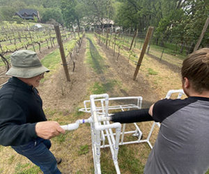
Bird netting is essential to protect your precious grapes form birds after veraison. However, anyone with their own backyard vineyard knows how difficult it can be to apply the netting and also role it up compactly for storage after harvest. With that in mind, a home winemaker came up with two DIYs to make the tasks easier.

A lot of thought and planning should be done before you begin designing a home winery. Whether building a new space or refurbishing an existing area, you want to make the winery as conducive to your needs as possible. From accessibility to temperature control, we lay out what you need to know.