 Recently Brew Your Own magazine did a story about the pneumatic bottle capper that I had built to cap beer bottles. A short time later, I was contacted by WineMaker Magazine asking if I’d be interested in making something similar, only this time one that was able to cap standard 750 ml champagne bottles. Of course I was up for the challenge, so I went back to the drawing board to see what I could come up with.
Since I was quite happy with the air cylinder I had used on my beer bottle capper, I decided to use the same one again. It’s a 2” bore, single-acting, spring-return pneumatic cylinder. The nice thing about this particular size and model is that the threads on the end of the cylinder rod are an exact match for the threads in a standard capping bell, which means that the bell screws right on without any modification necessary. Also, the force generated by this cylinder is just right for crimping crown style caps – not too high and not to low. To show this, I’ll compare the force of my pneumatic capper to that of a standard bench capper. The force output of any pneumatic cylinder is the area of its piston multiplied by the PSI of the compressed air. This cylinder has a 2-inch (5-cm) diameter bore which means the piston area equals pi x (1)2 or 3.14in2. At 100 PSI, the cylinder will exert 3.14in2 x 100 PSI, or 314 lbs. of force. Now if you look at a bench capper, you’ll see that the lever on it is about 10 inches (~25 cm) long, and the distance from the pivot point to the capping point is 1.25 inches (3 cm). This means that the force exerted at the capping point is eight times greater than the force applied at the end of the handle (10/1.25 = 8). So, figuring backwards, in order to get a 314-lb. force at the capping point you would need to apply 39.3 lbs. at the handle (314/8=39.3). When I did this on my bench capper it capped a bottle very nicely.
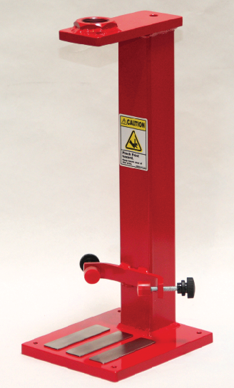
I wanted to keep the same basic frame design because of its simplicity and sturdiness. The concept involves using a section of 2-inch (5-cm) square steel tubing sandwiched between two 1⁄2-inch (1.25-cm) thick steel plates. The cylinder mounts to the frame by a properly sized hex nut welded onto the top plate. This is much easier than drilling and tapping such a large threaded hole into the steel plate. The bottom plate is wider in order to accommodate the wider champagne bottles and to keep the capper nice and stable on a flat surface. I chose a frame height such that when a standard 750ml champagne bottle was in place, the cylinder would extend to roughly ½” less than of the end of its stroke. This ensures that the cylinder won’t bottom out before capping, yet allows for plenty of room to load and unload bottles when the cylinder is retracted.
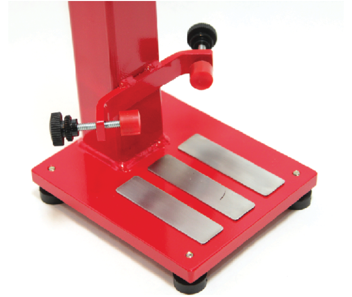
In order to position the bottles quickly and accurately when capping, I decided to weld a bracket to the frame that holds two adjustable bumpers positioned at 90° apart. The stoppers would act as a backstop that could be adjusted in or out to accommodate any variations in bottle diameters.
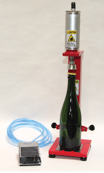
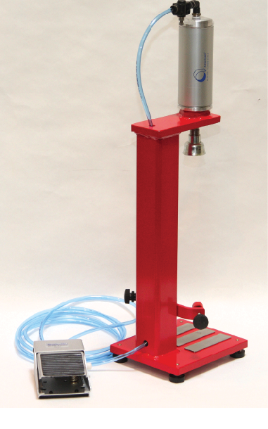
After the frame was welded up, I prepped it for paint and gave it a coat of primer and two coats of gloss red enamel. Once it was dry, I screwed in the four rubber leveling feet, installed the air cylinder, and screwed on the capping bell. Then I assembled and installed the two adjustable backstops. The air tubing was routed through the capper’s frame and connected to both the air cylinder and a foot pedal-operated pneumatic valve. Finally, I connected the foot pedal valve to my air compressor, turned it on, and took it for a test run.
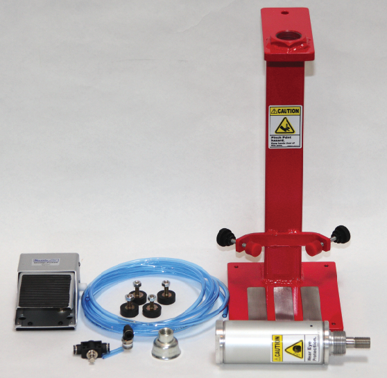
Materials and Parts:
Steel for frame:
(1) 2-inch square by 0.135-inch wall tubing, 15+” inches long
(1) ½-inch plate, 2½ inches x 6 inches
(1) ½-inch plate, 6 inches x 7 inches
(1) ¼-inch bar, 3/4 inch wide x 6 inches long
Capper:
(1) 2-inch bore by 2-inch stroke single-acting spring return air cylinder with a 5⁄8-18 thread (American Cylinder part #: 2000SN-2.00)
(1) 11⁄4-inch-12 thin hex nut (aka: a jam nut)
(1) 1⁄4 NPT by 1⁄4 OD push-to-connect 90° air fitting
(1) 29-mm capping bell
(2) ¼-20 x __” set screws
(2) ¼-20 Urethane bumpers
(2) ¼-20 Knobs w/o studs
(2) ¼-20 Knurled locking nut
(4) Rubber feet
(1) 3-way 2-position pneumatic foot-operated pedal valve and air fittings
1⁄4-inch OD polyurethane air tubing, 6+ feet
Air compressor
1. SKETCH UP PLANS Begin by sourcing out all of the parts and components you will be using. This might take a little determination and a lot of searching but the effort spent here could save you a lot of money in the end. Also, as you gather your components begin sketching up your plans, get a few sample bottles and take some measurements. Make sure that your frame is sized so that your air cylinder will cap bottles completely before reaching the end of its stroke. You might even have to wait until all your components are in hand before you can finalize your dimensions. A copy of my plans are available at www.huizingh.net/capper.
2. BUILD THE STEEL FRAME If you have the tools and skills to make this yourself, then by all means give it a go. First, cut your steel pieces to size, then drill two holes in the top plate — one for the cylinder rod to pass through, and one to route the air tubing. Drill a hole in the back of the square tubing for the tubing to exit. Also drill and tap holes in the base plate if you will be using screw-in feet. Securely weld all of the pieces together, making sure that the large hex nut, top plate, and bottom plate are all aligned properly and that they are as parallel to each other as much as possible. Form the bracket for the bottle guides and weld that on as well. Finally, clean and paint the frame. Note: For those of you without access to machine tools or a welder, consider taking your plans to a local weld shop and have one made up for you.
 3. ATTACH FEET, AIR CYLINDER AND BELL Once the paint has dried, screw in or attach the four rubber feet. Now screw the air cylinder into the large hex nut on top of the frame and tighten it with a wrench. Next, attach the capping bell by screwing it onto the end of the cylinder rod.
4. INSTALL BOTTLE GUIDES Assemble the adjusting knob assemblies by first screwing a small knob onto one end of each set screw. I used a little bit of thread lock to keep these from coming loose. Then screw the locking nuts most of the way on. Now screw the assemblies into the bracket on the capper frame. Finally, screw the bumpers onto the inner ends of the set screws, again using a little thread lock.
Safety Tip: You can attach a clear plexiglass shield in front of where the bottle rests so, in case a bottle breaks, there is a barrier between you and the glass. Wearing safety glasses is recommended due to the potential of a bottle breaking if the bottle is not lined up correctly or the capper is not operating as designed.
 5. INSTALL AIR FITTINGS AND CONNECT AIR TUBING Screw the 90° push-to-connect air fitting into the top of the air cylinder. Also, screw a push-to-connect fitting into the output of your foot pedal valve. Attach the polyurethane air tubing to the two fittings. (You could also use polyethylene tubing, which is less expensive but is also less flexible). On the input of the foot pedal valve, screw in whatever fitting you need to connect to your air compressor.
6. CONNECT TO AIR COMPRESSOR AND TEST CAPPER Now you should be ready to fire up your air compressor and connect it to the input of the foot pedal valve. You may want to start at a low PSI at first as you put it through the initial motions. Also, if you find that the air cylinder moves too fast (as they often do), you might need to put a flow control device somewhere in the air line to slow it down. Once you’ve got the cylinder moving up and down smoothly, it’s time to try it out for real. Set a bottle in position and place a new cap on top. Make sure your hands are clear then press down on the foot pedal and hold it down until the cap has been completely crimped. Now release your foot and you should be left with one perfectly and effortlessly capped bottle. Safety Tip: Never put your hand between the capping bell and the top of the bottle. Put the bottle cap on top of the bottle before placing the bottle below the capping bell.

Late harvest wines are made using grapes affected by the mold Botrytis, which dehydrates the grapes. We’ve pooled advice from three pros with numerous accolades for their dessert wines to help you make an award-winning late harvest wine at home. Joe Hudon is entering his 5th harvest as the Winemaker at Claar Cellars, an estate winery atop the White Bluffs area of the Columbia River in Pasco, Washington. Joe has been in the…
An aroma kit will help improve your ability to pick out aromas in a glass of wine. You can buy a kit for over $100, or make your own for a fraction of that.