DIY Bird Net Applicator
A few years after I had planted my vineyard I thought I had a decent harvest coming. But as the grapes sweetened, they began to disappear. At first, I thought the deer were getting over the fence and into the vineyard. No, it was the birds. That was my introduction to the need for bird netting.
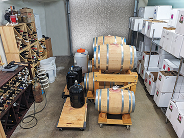
Since then, I apply my bird netting about a month before harvest. My netting for each row of vines is 14 feet (4.2 m) wide and 150 feet (46 m) long. I unroll the netting over the top of the vines and clip the bottom edges together to form a tunnel around the fruit, shoots, and leaves. During harvest, I remove the clips but leave the netting over the vines and pick underneath the netting. After I have destemmed and crushed the grapes and started fermentation, I have time to pull the netting off the vines and onto the ground between the rows. The final step in the process is rolling up the netting.
My netting is the plastic weave type. The way I have collected the netting for years was rolling it up starting with my hands, folding it into a roll about 2 feet (0.6 m) wide, but once I’ve rolled up 10–15 feet (3–4.5 m) in my hands, it becomes too bulky and I lay it down on the ground and roll it up from there. The roll would become wider and bulkier as I would go. I’d have to fold the ends in to keep it from getting too wide. And, of course, I’m walking, bent over, pushing the roll of netting.
Unrolling this bulky and tangled roll for the following harvest also had its problems. I would lay the roll on the top of vines and unroll it from there, but it would snag on the shoots and posts. Every 10–15 feet (3–4.5 m), I’d have to pull the netting tight, otherwise it wouldn’t be long enough to complete the row. A couple of years of doing this and I knew that things had to change.

Back to the Drawing Board
I wanted to design a “Bird Netting Applicator” made primarily from PVC pipes and fittings. The objective was to continue to roll up the netting with it laying on the ground and to be able to unroll the netting from above the vines. The applicator would consist of two parts, a roll-up device and a roll-out device. It was obvious from the start that the Roll-Up Applicator (RUA) would be more complicated than the Roll-Out Applicator (ROA). When I had new rolls of bird netting, they were rolled onto a cardboard tube and they were easy to unroll over the vines. So the objective was to roll up the netting like a new roll.
So, the RUA design had to pull the netting up from the ground, pull the netting into about a 30-inch (0.75 m) or so width, and roll it tightly around a tube. The Roll-Out Applicator design had to hold the tube and netting above the vines and keep the netting taut as it is being unrolled.
Considerations for the Build
As can be seen in the photos, building the RUA is complicated, but is divided into steps. You may feel more comfortable if you build it with a dry-fit (without PVC cement) to ensure that any mistakes can be easily corrected. After you feel comfortable that everything fits as it should, you can then re-assemble each piece using glue to hold them in place. Or, if you are comfortable with it, it may be easiest to dry-fit only one or two steps at a time, then glue-in each piece from those steps. Note that dry-fit joints can be difficult to undo if the pipe is forced fully into the fitting, so make your dry-fit snug, but not tight.
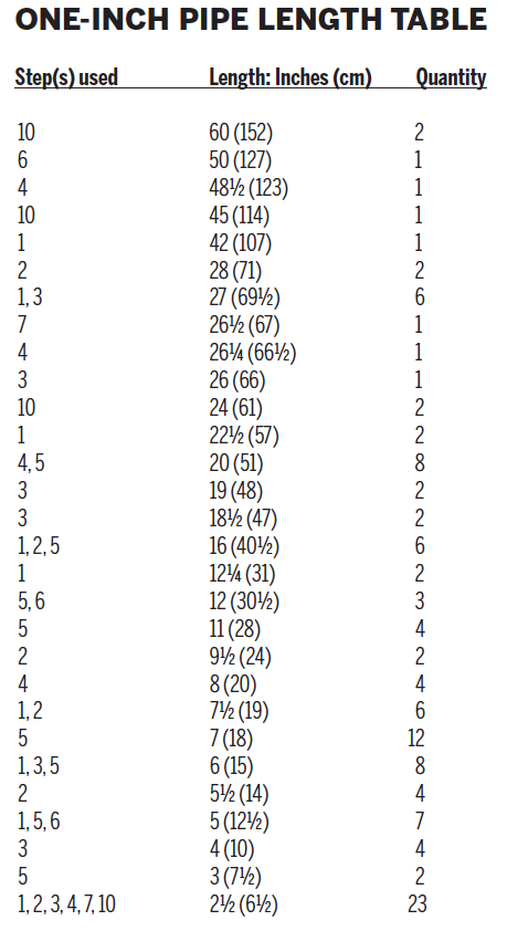
The RUA and ROA are made using 1-inch (2.5-cm) PVC, Schedule 40, pipes and fittings with the exception of the net spindle and some of its associated fittings that are 1¼-inch (3- cm), Schedule 40. Some types of fittings don’t exist and two fittings are required, connected closely together. Since nearly all pipes in this build are 1-inch (2.5-cm) diameter pipe, an “18-inch (45-cm) pipe” will refer to its length. I will make it clear in the steps that are not using 1-inch (2.5- cm) diameter pipe.
Having priced out this project, the cost for fittings should run about $175 if bought locally or about $110 if purchased from a website like SupplyHouse.com. PVC pipe for the build and pipe for each roll of netting (assume 12 rolls), purchased locally will cost about $100. Miscellaneous items (wheels, axle, snap pins, etc.) will run another $25. That brings the total cost to about $300 or $235 if fittings are purchased online.
Keeping fittings square is essential and, therefore, when gluing in some fittings, temporarily insert an 18- to 24-inch (45- to 60 cm) PVC pipe into the appropriate outlet and eyeball the connection to be square. Since PVC pipes are fairly flexible, a little misalignment will be alright. Be sure to remove the “temporary pipe” (TP) immediately as it could get stuck if too much solvent or glue is used and it runs into the other outlets.
Pipe lengths must be accurately and squarely cut. I suggest using an electric power chop saw. When gluing a pipe to a fitting, be sure the pipe is all the way in and does not push slightly out before the glue sets. If you notice a pipe and fitting that is not the same length as its symmetrical counterpart, then the longer one is probably too long and you might be able to trim it down. Minor variation in length is tolerable and won’t make a difference.
I have divided the DIY build into 10 steps. Each step is fairly complicated in itself, but there is a photo for each step with pipe lengths identified. (If you notice a coupler fitting in the photos, just ignore it as it was necessary to fix a construction mistake or design error.) The fitting type should be visually identifiable in the photo. With each step, the RUA will grow, but only the additional pipes will have their length identified on the photo. With only one exception, the RUA is symmetrical, so only one side has the pipe length identified.
In the following steps, I will refer to the rectangular back portion of the RUA as the base, the front sloping portion as the net ramp, the top portion above the base as the winder mechanism, the winder and handle as the winder crank, and the pipe on which the netting is wound around as the net spindle. Also, a “temporary pipe” will be referred to as TP, and a short “connector pipe” (normally 2 ½ inches/6.4 cm) will be referred to as CP. With that, let’s dive in!
Steps for the Build
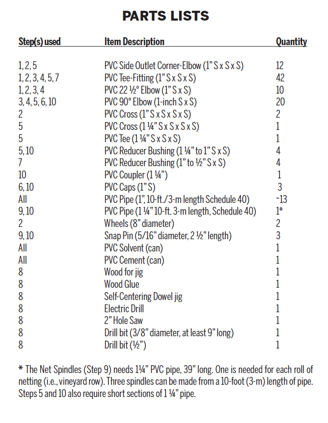
There are 10 steps for the build. The words “glue-in,” “insert,” and “add” are used synonymously, however a TP is never glued-in. For each step, refer to the instructions, the photos, parts list, and pipe length table. The PVC fittings are identified on the Parts List at the end of this article. Likewise, the PVC pipe lengths are identified on the pipe length table and photos. You may want to cut all the pipes to length before starting the construction (cut longest pipes first and mark the pipe length on each pipe with a permanent marker).
Step 1 – Bottom/Sides of Base. You may wonder why the Base has 22 ½-degree elbows that slope the back of the RUA. That feature is to allow moving the RUA by holding onto the back cross-member of the Base without stepping onto the bottom back cross-member as you walk. So, don’t eliminate this feature.
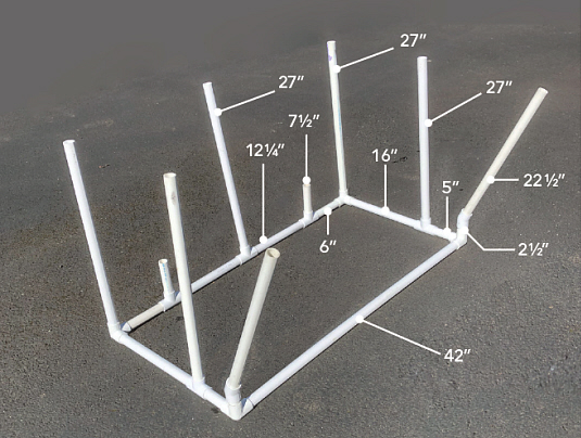
Beginning construction:
- Lay out the four corner-elbows and five tee-fittings of the Base on the ground. Dry-fit a TP into the side-outlet of each rear corner-elbows (rear – where the “slope” pipes will be installed). Lay them flat on the ground. Now glue-in a 42” horizontal pipe between the two rear corners and, before the glue sets, ensure the corners are square with one another before removing the TPs.
- Insert all vertical pipes (27”, 7 ½”, & 2 ½”) into the remaining corner-elbows and tee-fittings as shown in the photo.
- Glue-in the horizontal pipes (5”, 6”, & 16”) for the remaining outlets on the corner-elbows.
- Glue-in the tee-fittings and remaining horizontal pipes, ensuring each vertical pipe to the horizontal pipe is square.
- Insert a 22 ½-degree elbow to 22 ½” slope pipe, and then align to slope rear and glue-in (there should be marks on the 22 ½-degree elbow to aid in this alignment). Repeat for the opposite side.
Step 2 – Top of Base. The purpose of the Base is to hold the Winder Mechanism at height for a standing operator. The Base must also be rigid enough to take the strain of winding the netting onto the Net Spindle.
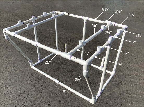
Start from the rear of the Base (from the slope pipes) and pick a side to work on:
- With a TP inserted into a 22 ½-degree elbow, glue the elbow onto the slope pipe with the TP at true vertical.
- Remove the TP and glue-in a 2 ½” CP pipe.
- Insert TP into the side outlet of a corner-elbow, align TP with the side of the Base, and glue the corner-elbow to the CP.
- Build the rear horizontal cross member, starting with gluing-in a 5 ½” pipe into the flow-thru outlet of a tee-fitting.
- With a TP inserted into the side outlet of tee-fitting, glue-in the tee-fittings into the 5 ½” pipe with the TP level and extending forward.
- Repeat steps 1-5 for the opposite side.
- Glue-in a 28” horizontal pipe between the two tee-fittings.
Now build forward:
- Glue-in four 7” pipes into the corner-elbows and tee-fittings.
- Now, again pick a side to work on.
- Using TPs in the side outlets of two tee-fittings, glue-in with the TPs in vertical orientation.
- Glue-in the next two horizontal pipes (7” & 16”).
- Using a cross-fitting, glue it to the horizontal pipe and vertical pipe from the Base. Now glue-in a 7” pipe into the horizontal outlet of the cross-fitting.
- Like before, use TPs inserted into two tee-fittings, glue the tee-fittings into the horizontal pipes.
- Repeat steps 2-4 for the opposite side.
- Glue-in four 7 ½” horizontal pipes into the remaining tee-fittings.
Finally, build the front horizontal cross members:
- Start with gluing on the corner-elbow onto the horizontal pipe and vertical pipe from the Base on each side.
- Glue-in 5 ½” pipes on each corner-elbows
- Then glue-in tee-fittings to the unattached 5 ½” and 7 ½” pipes.
- Insert CP to the remaining outlet of the tee-fitting.
- Glue-in two 9 ½” pipes to a tee, align to the CP and glue to center vertical post from the bottom. (The remaining dangling pipes will be connected to a tee-fitting to the front ramp at about 45-degrees downward position in Step 4).
Step 3 – Bottom of Net Ramp. The Net Ramp has two purposes. First it lifts the netting off the ground and up to the Winder Mechanism. Second, it forces the width of the netting to be folded into about 30-inch (0.75-m) width before it rolls onto the Net Spindle.
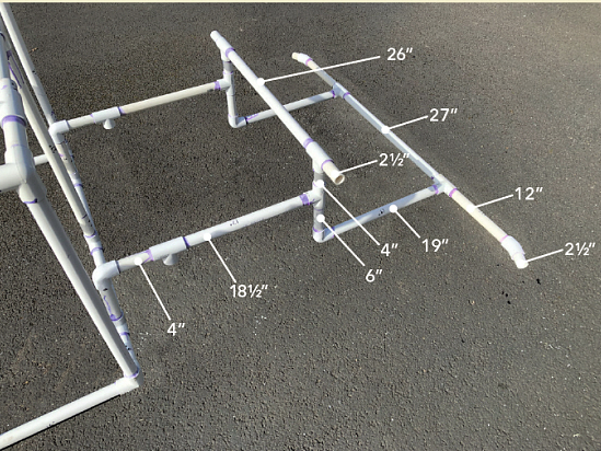
Start the build from the front of the Base, pick a side to work on:
- Insert an elbow onto the 7 ½” vertical pipe on the Base using TPs oriented forward.
- Add a 4” pipe facing forward.
- Glue to the flow-thru outlet of tee-fitting, aligned using a TP, which will be connected to the wheels. (You may want to tip the Base onto its rear in order to have room enough to insert TPs).
- Insert 18 ½” pipes into the flow-thru outlet of the tee-fitting.
- Using a TPs again, insert the side outlet of tee-fittings onto the 18 ½” pipe.
- Now insert 4” pipe on top and 6” pipe on the bottom of the tee-fitting.
- Repeat steps 1-6 for the other side.
Now working both sides:
- Using TPs, glue onto both ends of a 26” pipe flow-thru outlet of a tee-fitting.
- Insert CPs to the remaining flow-thru outlets of the tees.
- Glue this unit on top to the 4” pipes.
- Next glue-on an elbow onto 19” pipe and glue the elbow onto the 6” pipe, extending forward.
- Repeat step 4 for the other side.
- Now using TPs, glue onto both ends of a 27” pipe flow-thru outlet of a tee-fitting.
- Add 12” pipes to the remaining flow-thru outlet of the two tee-fitting.
- Glue-in a 22 ½-degree elbow and a CP on each side of the bottom cross member, keeping the elbow flat (i.e., in the same plane as the tee on the bottom cross member).
- Finally, glue the side-outlet of the two tee-fittings of this section to the 19” pipes.
Step 4 – Top of Net Ramp. The top of the net ramp has two ducts to force the netting together into a 30” width. The ramp rises at about a 45-degree angle and narrows at a 22 ½-degree angle.
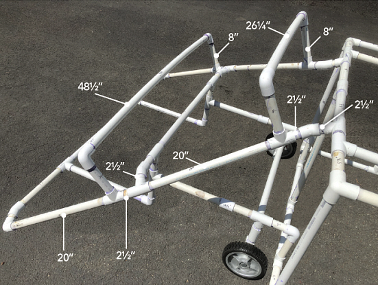
In completing the Net Ramp, start on one side of the bottom cross member:
- Glue-on a 22 ½-degree elbow and a CP on the middle cross member, keeping the elbow flat (i.e., in the same plane as the tee on the middle cross member).
- Build up a section starting with an elbow and a 20” pipe and add a tee at the flow-thru outlet at the opposite end, perpendicular to the elbow.
- Insert an 8” post into the side outlet of the tee, a CP into the flow-thru outlet, and another tee perpendicular to the previous tee.
- Glue-in this built-up section to the bottom and middle cross members.
- Glue in a 20” pipe to the last tee.
- Insert an 8” vertical post into the side outlet of a tee and CP on the flow-thru outlet, then insert it into the 20” pipe.
- Glue-on 22 ½-degree elbow to the CP with the elbow in the same plane, but bent outward as shown in the photo.
- Glue-on a CP to the 22 ½-degree elbow and then to a side outlet of a tee-fitting, keeping the flow-thru outlets in the same orientation as the top of the Base.
- Now glue the tee into the top of the Base with two unconnected pipes. This will require some pulling and pushing.
- Repeat steps 1-9 for the opposite side of the ramp.
Now to complete the net ducts:
- Insert TPs onto two elbows.
- Glue elbows on each end of a 48 ½” pipe, keeping the elbows square.
- Glue this section to the lower 8” vertical pipes on the ramp.
- Repeat steps 1-3 using a 25 ¼” pipe.
- Glue this section to the upper 8” vertical pipes on the ramp.
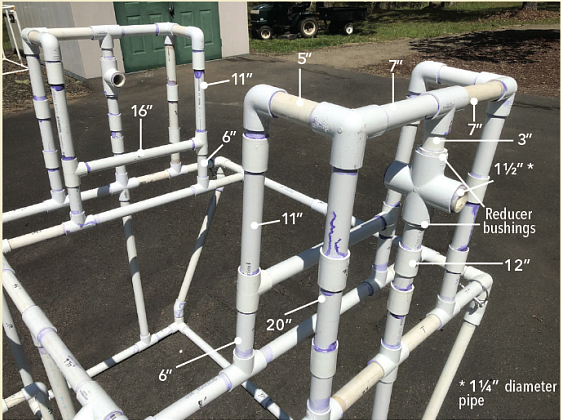
Step 5 – Winder Mechanism. The Winder Mechanism has two functions. First, to hold the winder in a rigid manner at a suitable height. Second, to keep the netting in the middle 30 inches (0.75 m) of the Net Spindle. In addition, the horizontal pipes underneath the 1 ¼” cross-fitting and tee-fitting will catch the Net Spindle when the Winder Crank is pulled out when changing Spindles.
Start with one side of the Base:
- Glue-in two 20” vertical pipes, two 6” vertical pipes, and a 12” vertical pipe as shown in the photo. (Ignore the couplers in the photo.)
- Insert TPs into the flow-thru outlets of two tees, and glue-in a 16” pipe into the side outlet of the tees.
- Glue-in this section onto the 6” vertical pipes.
- Glue-in two 11” pipes into the tees.
- Insert TPs into an elbow and a corner-elbow and glue-in a 5” pipe between the two elbows. Note: Check with the photo and dry fit steps 4-5 first before gluing.
- Glue this section onto the 11” and 20” pipes as shown in the photo.
- Repeat steps 4-6 for the other side except twist the elbow and corner-elbows (mirror image).
- Repeat steps 1-7 on the opposite side.
This is the only step that does not have symmetry and the user has a choice to place the crank on the winder on the left or right side. In my RUA, I have placed the crank on the left side (as viewed from the back) because I am right-handed. The center vertical pipe has a 1 ¼” cross-fitting on the crank side and 1 ¼” tee-fitting on the opposite side.
- With the 1 ¼” cross-fittings, insert a 1 ¼” to 1” reducer bushing on the top and bottom outlets.
- With a 1 ¼” TP in the horizontal outlet of the cross-fitting, glue it in the crank side on the 12” vertical pipe.
- Glue-in a 3” length pipe into the top side outlet of the cross-fitting
- Glue-in two 7” pipes into the flow-thru outlets of a 1” tee.
- Glue this unit to the top of the 3” pipe and the two corner-elbow-fittings (it will require some pushing and pulling).
- For the opposite side, using a 1 ¼” tee, repeat steps 1-5.
- Don’t overlook this step: Using three 1 ½” lengths of 1 ¼” pipe, glue-in into the remaining outlets: One in the tee-fitting and two in the cross-fitting.
Step 6 – Winder Crank. At this point it should be noted that 1” PVC pipe has an outside diameter (OD) of 1.315” and 1 ¼” PVC pipe has 1.380” inside diameter (ID). Hence a 1” pipe will slide into the 1 ¼” cross-fitting and tee-fittings as describe in Step 5.
This step is straightforward and the user may decide on larger or smaller crank handle diameter. Of course, the mechanical advantage is to make the crank diameter large. The 1” rotating shaft, which is 50” long, slides through the Winder Mechanism and is connected by elbows to the crank handle. I chose 12” for the crank handle diameter and 5” for the handle.
Step 7 – Wheels. The purpose of wheels is to be able to move the RUA around. For short vineyard rows, the RUA would probably remain stationary, while on longer rows, the RUA may move down the vineyard row as the netting is pulled into the RUA. Also, wheels are needed in moving the RUA from one vineyard row to the next. I went with wheels that are lightweight, flat-free, 8” in diameter, and for a 5/8” diameter axle.
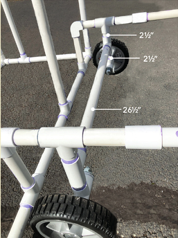
A ½” PVC pipe has an ID of 0.622” and 5/8” is 0.625”. That is close enough for a 5/8” steel bolt to fit tightly into a ½” fitting. Even better is a bolt that is not threaded its full length, as the unthreaded portion has a slightly smaller diameter. Flat washers should be used between the wheel and fitting, and the fitting and nut. The nut should be self-locking. Use 1” to ½” reducer bushings on the tee-fitting. This setup allows the front of the RUA to be raised about 8”.
To keep the wheels from twisting, a 26 ½” semi-axle is inserted, as shown in the photo.
Step 8 – Pin Hole Jig. The Winder Crank slides into the Net Spindle and two are held together by snap pins. The jig is used for drilling 3/8” holes for 5/16” diameter snap pins.
The Net Spindle is just a section of 1 ¼” PVC pipe with holes for a snap pin on either end. The pinholes on the Net Spindle must align with the Winder Crank holes, which can be difficult to do. Furthermore, a Net Spindle is needed for each roll of netting. This can be easier and more accurately done with a Pin Hole Jig.
The Pin Hole Jig is made of ¾” (11/16”) plywood, solid wood, or both. The directions below will refer to plywood. A chop saw will work well for most of the cuts. Jig also requires the use of a self-centering 3/8” diameter dowel jig, but a drill press could be used. Also, a 3/8” drill bit at least 9” long will be needed.
Making the V-groove piece:
- Cut a piece of plywood 3” by 9 3/16” (the 3/16 width of a sawblade will be lost when the plywood section is cut into two).
- Mark (with pencil) a vertical line at 4 ½” from the left side.
- Mark a horizontal line at 2 1/8” from the top.
- Mark a 45-degree line through the intersection of the two lines, with the line starting at the top going towards the right-side bottom.
- Mark the right-hand side a 45-degree line, starting at the intersection going up and to the right.
- Now cut along the right side of the 45-degree line from top to bottom.
- Cut the right-hand piece along the 45-degree line.
- The two pieces should fit together forming a V-groove at the top.
Making the pipe holder:
- Cut two pieces of plywood 3” by 9”.
- Cut 2” circular hole in the center, 1 ½” from the top on both pieces.
- Glue these pieces on either side of the V-groove piece with the circular holes over the V-groove.
- Brad nail, screw, or clamp these pieces together.
Make a second copy of the V-groove piece and pipe holder.
Attaching to the base of the jig:
- Cut a piece of plywood 9” by 40” for the base of the jig.
- Attach the pipe holders at about 1” from each end of the base of the jig such that the centers of the V-grooves are 35” apart.
Attaching the “Dowel-It” jig (other dowel jigs may have to be attached differently, or if a drill press is used, the following setup will need to be different):
- Cut a piece of plywood 9” by 4”.
- Cut a 2” circular hole in the center at 2 ½” from the top.
- Cut the piece down to 9” (as is) by 2 7/8”, the cut passing through the circular hole.
- Attach the bottom of the dowel jig tightly against the above piece.
- Insert this piece in-between the two outer layers of the pipe holder.
- Align the dowel jig to the V-groove and clamp tightly.
- Drill through this piece using the dowel jig.
- Recheck the alignment in step 6. Very critically, the dowel jig must be square with the center of the V-groove (otherwise the holes in the pipe will not be through the center of pipe and the pins holes will not be aligned).
- Attach this piece with screws.
- Drill through the dowel jig an inch or so into the V-groove.
- With the other pipe holder, drill an inch or so into the center of the V-groove.
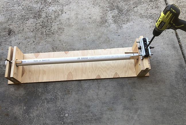
Step 9 – Pin Holes in the Winder Crank and the Net Spindle.
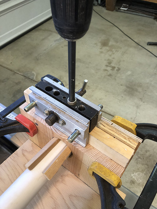
Start with making pinholes in a Net Spindle:
- Mark (with a Sharpie) a 39” section of 1 ¼” pipe at 2” from the end of the pipe.
- Insert pipe into the jig and align the mark to the dowel jig.
- At the dowel end of the jig, insert two shims at the 10:30 and 1:30 positions around the pipe to hold it in the V-groove.
- At the opposite end, insert a single shim at the 12:00 position.
- Using the dowel, drill through the pipe.
- Remove pipe and examine the holes for alignment (particularly, if offset to one side or other side of the pipe).
- If problems, check the jig; otherwise flip the pipe end for end and insert into the jig.
- Insert a pin, drill bit, or something similar to hold the pipe steady in the just drilled end.
- Insert shims as before and drill the second set of holes.
That completes the first Net Spindle, which is now used to drill the holes in the Winder Crank:
- At the RUA, insert the Winder Crank into the Net Spindle.
- Now mark (with a Sharpie) the Winder Crank through the two holes at each end of the Net Spindle.
- Return to the Pin Hole Jig, insert the Winder Crank.
- Align marks to dowel jig, insert the shims as before, and drill.
- Flip, insert shims, and drill the second set of holes.
- Now, because alignment tolerances are not perfect, drill out these holes with a ½” bit.
- Test the alignment by returning to the RUA and inserting Winder Crank, Net Spindle, and snap pins. If the snap pins don’t fit, then check your jig and procedure. When you find your problem, adjust accordingly and drill a second set of holes (90 degrees rotated) on the Net Spindle.
To make additional Net Spindles, the process can be sped up by modifying the Pin Hole Jig:
- Determine the added width to the jig such that 2” mark is aligned to the dowel jig.
- Find layers of plywood with a thickness that matches the added width needed.
- Cut 2” circular holes at the appropriate locations on the added layers.
- Clamp these layers plus a solid layer on the back of the Jig.
- Now marking the 2” location on Net Spindle can be skipped.
- Insert a 39” section of 1 ¼” pipe, insert in jig, lock in with shims, and drill.
- Flip, insert pin, shim, and drill
- Again, test the new Net Spindle for fit in the RUA.
- Repeat steps 6-8 for each Net Spindle.
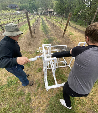
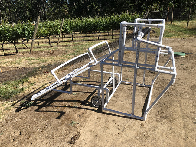
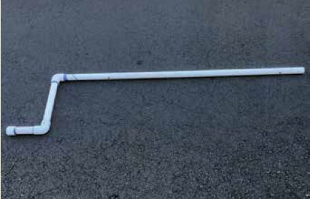
Step 10 – Roll-Out Applicator (ROA). The ROA is used to unroll the bird netting that has been wound up on the Net Spindle. It requires two people, one on each side of the vineyard row, to hold a PVC post attached to the roll out mechanism.
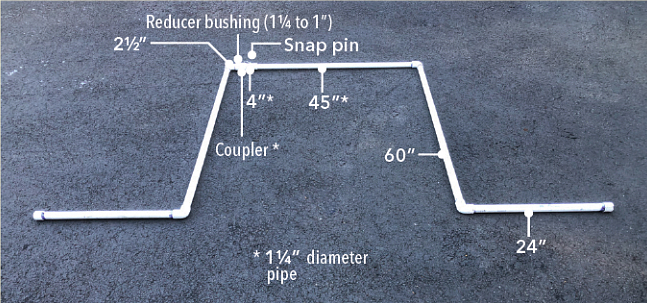
The assembly of the ROA is straight forward. The only element that might be modified from my version is the length the post and the leverage bar would be dependent on the height of the vines and height and strength of the operators. The ROA consist of two sides.
Lay out the pipes and fittings as shown in the photo, and keep the Pin Hole Jig (Step 8) nearby. Start with the side with the 1 ¼” to 1” reducer bushing:
- Glue an elbow onto a 60” pipe
- Insert a CP into the elbow.
- Glue the reducer bushing onto the CP.
- Glue on a 1 ¼” coupler on to the bushing.
- Next take an 18” to 24” pipe and glue-on an elbow on one end and a cap on the other end.
- Glue this section onto the 60” pipe, keeping the unit square and as shown in the photo.
Next, the other side is built:
- Glue an elbow onto an 18” to 24” pipe on one end and a cap on the other end.
- Glue a 60” pipe into the elbow.
- Using a TP inserted into an elbow, glue an elbow on the above section, keeping it square and as shown in the photo.
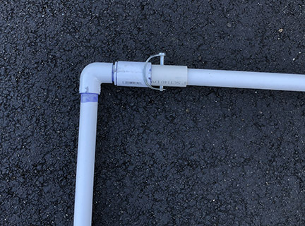
Connecting the two sections together:
- With a 1 ¼” pipe at least 10” long, insert it into the Pin Hole Jig and drill holes at the 2” mark.
- Cut the pipe with the hole in it down to 4”.
- With a 1” pipe 45” long, insert it into the Pin Hole Jig and drill holes at the 2” mark.
- Increase the hole size to ½” on the 45” pipe.
- Slide the two pipes together, align the holes, and insert snap pin.
- Glue the two sections built above onto this section as shown in the photo.
Operating the RUA
Take the winder crank and push it through the opening on the winder mechanism. Slide the winder crank through a net spindle and into the opening on the opposite side. Align the holes in the net spindle with the holes in the winder crank, insert snap pins, and close the locking snaps.
With the bird netting on the ground, place the RUA near the end of the netting. Wrap a 6- to 8-inch (15- to 20-cm) strip of Duct Tape around the center of the net spindle. Repeat with Duct Tape at about 12 inches (30 cm) on either side of the center. Take the end of the netting and fold it together such that it is about 30 inches (75 cm) wide, and hook it onto the Duct Tape.
Start turning the winder crank while moving the RUA several feet forward until the bird netting has been wrapped around the net spindle a couple of times. If the vineyard row is long, you may have to move the RUA forward as you wind more netting on. Keep some tension on the netting so it is wound tightly.
Once you have completed a section of netting, tie a string around the roll of netting. Pull the two snap pins out, and then pull out the winder crank. Remove the netting with the net spindle from the RUA.
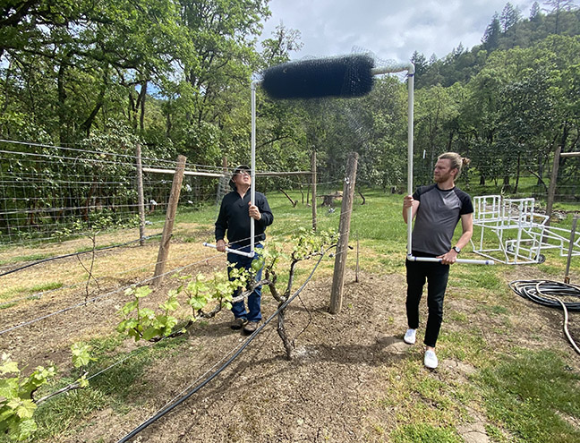
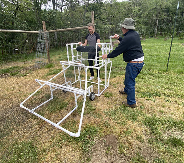
Operating the ROA
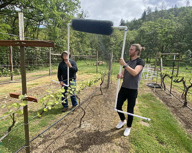
Take the un-roll pole with the insertion arm and insert into a net spindle loaded with bird netting. Take the other un-roll pole and slide it over the exposed insertion arm. Align the holes and insert a snap pin and close the locking snap.
Hook the bird netting onto the start of a vineyard row and, with a person on each side of the row holding one of the un-roll poles, walk together down the row. The netting will be on top of the row and the sides of the netting will have to be pulled down onto the sides of the row.